

How Oes Rpm Tranmit From a Bevel-bevel Gear UPDATED
How Oes Rpm Tranmit From a Bevel-bevel Gear
Abstract
The design of bevel gear for employ in the development of revolving rostrum is presented. The pinion gear is designed to rotate at 1400 rpm for the output gear of 23 rpm. A suitable gearmotor was selected for the design based on the bevel gear design analysis. The motion is transmitted to the rostrum via a shaft keyed to it with a gib-head key and assembled on the rostrum with a spline connector. The analysis of the bevel mesh shows that maximum deformation of almost 26.552 mm occurs in the pinion due to the loading the pinion molar. The deformation of the tooth is observed to affect considerable the performance of the system. The transmission efficiency of the machinery was obtained as 86% though effective for the operation of the organisation but could be improved by a more than careful material selection for the bevel gear mesh.
Share and Cite:
Raji, N. , Adedeji, M. , Oyetunji, E. and Agbelusi, A. (2021) Blueprint Assay of Bevel Gear for Gearmotor Selection in Revolving Platform. Modern Mechanical Engineering science, xi, i-11. doi: ten.4236/mme.2021.111001.
1. Introduction
The design of rostrum had undergone quality development over the years depending on the specific areas of application ranging from award presentation to public address functions and church building activities. Unlike pattern of the rostrum has evolved in contempo time to incorporate conveniences in reaching the targeted audition. The blueprint of rotary rostrum could be a convenient concept of its usage in large halls. Several mechanisms could be used to achieve rotary motion ranging such as pulley systems, gear systems, sprocket and chain, and worm and worm wheel among others. The option of the bevel gear mesh mechanism for rotary motion of the rostrum is discussed in this commodity. The choice of the bevel gear mesh mechanism is centered on the possibility of reversing the management of rotation every bit it is required for rostrum operation and to increase or decrease the speed of rotation. Bevel gears are widely used to transmit motion and ability via shafts bundled at angle of 90˚ [one]. Its usage is conspicuously plant in gearbox.
Bevel gears have teeth cut on conical blanks. The gear pair is used to connect nonparallel intersecting shafts for motor manual, differential drives, and mechanical instruments. The application of bevel gears could be plant in locomotives, railway tracks, ability plants, press press machines among other applications. Bevel gear meshing every bit a transmission mechanism has been extensively used for the concept of transmitting rotary motion in machines. Screw bevel gears are used in the design of helicopter power transmission systems [two]. The bevel gears in the helicopter systems were designed to transfer power from the horizontal engines to the vertical rotor shaft. The selection is the ability of the gears to carry loftier loads and operate at very loftier rotational speeds. The possibility of realizing large angular move in machinery has likewise given credence to its use in Photo Voltaic tracking organization [3]. The likely failure of the machinery is usually due to dynamic load and wears which causes angle and wearable of the gear teeth. Geometric programming technique has been used to optimize the design procedure of the gear mesh for purpose of limiting such effect. A contact stress capacity model could be adult for the straight bevel gear using geometric approximation as presented in [4]. The successful use of the bevel gear machinery for car performance relies on the optimum design consideration for the gears contact forces, geometrical gear equivalence, and the contact fatigue assay. Several authors accept dwell on the optimization procedures for the design of bevel gear mechanism and the identification of the possible failures oftentimes encountered in bevel gear operations [5] [6] [7] [eight] [9]. In the concept of the rostrum, a pair of bevel gears with spherical involutes teeth transfer power and move over 180˚ with line contact.
2. Materials and Methods
The blueprint of the revolving rostrum is as shown in Figure 1. The rostrum equally designed consists of iii assemblies, the structure frame, the transmission system, and the control system.

Figure 1. Conceptual scheme for the revolving rostrum.
The construction frame is made upwards of the rostrum platform, the gearmotor drive enclosure brazed with angle iron frame. The transmission system composed of a gearmotor with a machined shaft assembled on the motor to back up the rotational movement of the rostrum platform. The control system is an electrical organisation design to allow for 180˚ rotation of the entire organization. The pattern for the structure frame and the transmission organization is discussed in this newspaper while the control system design will be discussed in another paper.
two.1. The Construction Frame Pattern
The frame stem is made of hollow steel pipes of 27 mm and 38 mm diameter. The two pipes are assembled using the screw knob for purpose of aligning betwixt one m to 1.iii k. The platform is made of 10mm thick steel plate for the top of the gear enclosure. The frame stem is assembled on the platform using a footstep flange. The gear motor is mounted on a seat plate of 23 mm × 12 mm, supported by ii angle plates of 70 by 70 mm width sizes welded to the cylindrical enclosure. The manufacturing process involve include cut, grinding, welding and the use of commodities and nuts where necessary for structural rigidity.
two.ii. Manual System Design
The manual organisation comprises the shaft assembled on the bevel gear mesh of a gearmotor assembly.
Bevel gear mesh design: In this case the straight bevel gear is intended for the design requirement of the gearmotor. The design of the bevel gear here is based on strength and the dynamic load input and output. The bevel gear configuration is as shown in Figure 2.
The thrust force on the gear and speed specification is given in Table 1.
The tangential forcefulness perpendicular to the airplane of the axes is obtained equally in Equation (ane)
(i)
ϕ and δ are the gears pressure and reference cone angles respectively.
The thrust force on the input pinion and output gear is obtained from Equations (2).
(2a)
(2b)
The input and the output torque could be obtained as expressed in Equations (three) and (4) [10].
(3a)
The torque load for the input gear is obtained as [4].
(3b)
(4)
The key reference diameter of the output gear in the gear unit of the motor gear should not exceed the range every bit determined in Equation (5).
(5)
The bending stress in the bevel gear when loaded could exist obtained from Equation (6) (AGMA 2003-B97) [11].
(6)
where is the angle stress, b is the tooth face width, is the overload factor, is the dynamic gene, is the outer transverse module, is the size gene for bending strength, is the load distribution factor, lengthwise curvature factor for bending strength, geometry factor for bending strength. The option of the various factors centered on the possibility of the uncertainty in the loading condition of the bevel gear mesh in rostrum operation. These factors could be determined and selected every bit detail in AGMA 2003-B97 [11]. The pitch-line velocity of the gear is often required for determining the factors and this is obtained as expressed in Equation (7).
(vii)
where and are the pitch diameter and speed of the pinion in the mesh.
Gearmotor choice: The gearmotor which consists of a gear unit and electric motor is selected for the manual system. The specification of the gearmotor is obtained from the forcefulness analysis of the rostrum function. The gear unit tends to reduce speed and increase the torque that may be required for the performance of the system. The most important parameters in regards to gearmotor are the speed torque and efficiency. The addition of a gear box is intended to limit the speed of the motor's shaft, and increment the motor's power to output torque. It is intended to evaluate optimum operational speed of the rostrum and then determine the torque required to meet the needed performance.
The basic size of the gearbox is obtained from the estimation of the output torque considering the anti-reversing specification of the arrangement for sudden restriction application in the rostrum desired position during operation. The specification for the gearbox pick procedure include the consideration for the operation cycle, upper bound input speed and the upper bound torque. The rostrum is designed for output speed range of 20 - 25 rpm assuming that the rostrum is operating at an extreme duty cycle of 24 hours per twenty-four hours with the rostrum operating nether uniform loading shock situation. The condom gene satisfying this consideration is obtained as κ (one.55). The output torque is obtained equally expressed in Equations (1)-(3).
A wide range of motor sizes and gearbox ratios could achieve the specific output torque and the speed, however conceptually in this example; a pre-engineered gearmotor is selected from the vendor's gearmotor curve. The gearmotor curve combines the operation of the motor and gearbox together past displaying torque and efficiency. The specification of the gearmotor for this pattern is obtained equally tabulated in Table two.
Output shaft blueprint with keys selections: The output shaft is assembled on the gearmotor output gear as shown in Figure 3. The shaft is machined to accommodate the gear hub diameter of twoscore mm and likewise at the bearing of the rostrum platform support. The bore of the shaft could be obtained from Equation (viii) as discussed in [12].
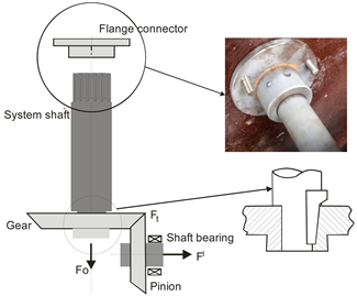
Figure 3. Geometric layout for the shaft.
(8)
α is the column activity factor which unremarkably ascend due to the phenomena of buckling of the shaft due to the axial load on the shaft. The value of α could be obtain as expressed in Equation (ix)
(9)
where , L is the shaft length and r is the shaft radius, .
Where km and kt are the angle and torsion factors accounts for shock and fatigue. The values of the factors are selected because suddenly applied load and modest shock condition for the blueprint. is the material yield strength, M is the bending moment due to the shaft loading, T is the torsion load on the shaft, Fo (Blueprint load) is the centric strength on the shaft as obtained for the bevel gear.
The specified parameters are shown in Tabular array three. The shaft is continued to the gearbox output gear via a gib head fundamental. The key is to avoid failure past crushing and shatter which could effect from the mild shock at the start of movement and end of move during operation of the machine due to wiggle and the gib head key of nominal height of 8 mm and width of 12 mm with 9 mm thickness is selected from standard DIN 6887/ISO 2497.
The spline connection is used for connecting the shaft to the flange carrying the rotating platform. The ISO 5480 is used for the connection design with involutes splines on the shaft and flange-hub. The pressure angle for the involutes cut is thirty˚. The spline design data is as shown in Table 4.
The involutes cutting ensure constant torque load, T, over the length, Lsouthward , of the spline. The torque deformation angle could be obtained as [13]
(10)
The involutes teeth are designed against deformation at the molar root [14] as expressed in Equation (eleven).
(11)
where P is the applied load and is the bending at which the load is applied to the organisation.
The stiffness of the tooth could exist obtained from the Equation (12) [14].
(12)
Modeling and assay: The bevel gear mesh assembly was prepared using the solid-work software and imported to the ANSYS workbench 15.0 for structural and dynamic analysis of the bevel mesh. The model was analyzed for the tooth deformation and bending stress.
3. Results Word
Figure 4 and Figure 5 show the distribution plots for the ANSYS.
Tooth root deformation: The structural stress analysis on the bevel gear mesh shows that the maximum deformation of the gear mesh is obtained as 26.552 mm.
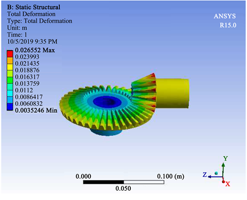
Figure four. Bevel gear deformation analyses.
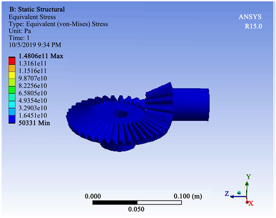
Effigy v. Bevel gear angle stress analyses.
The maximum deformation occurred on the pinion gear as shown in Effigy four. The figure shows the stress distribution resulting into the gear mesh deformation. The deformation at the pinion gear could be responsible for the lower torque manual to the gear.
Bending stress: The angle stress value at the root of the tooth is as distributed in Figure 5. The maximum bending stress is obtained as 148 GPa which is rather loftier for such design suggesting the possibility of iteration process for the material pick among several materials that could be available for the design rather than been specific with using mild steel equally is selected for the design. It is evident in gear pattern that the angle stress is ofttimes dependent on the gear face up width. It is a general study that the maximum bending stress could be reduced by increasing the face width of the gear molar.
Performance evaluation of the rostrum: The operation of the mechanism for the performance of the rostrum has been examined. The response of the rostrum platform under the turning upshot of the bevel gear machinery was investigated. The technical evaluation of the organization was carried out using arbitrarily chosen prepare of load values between 35 - 250 kg to evaluate the organization below and to a higher place blueprint load.
The result of the motion geometry is as shown in Figure 6. At the start and end of motion the performance of the rostrum suggest that there is probable to be a rate of change of dispatch showing the wiggle nature of the organization at the get-go of the motility equally a result of modify in the direction of motion from the forwards to the return motion and vice-versa. The behavior of the mechanism at this instant seems asymptotic even equally it becomes zero at the stop of the move which is

Figure six. Kinematic analyses for the rostrum motion.
not probable to be except the motorcar is intended to stop operation at that moment. This issue results in a light vibration of the organisation and is required to be smoothened for constructive performance. Evaluation of the bevel gear efficiency indicated a transmission efficiency of 86%. The lubrication of the mechanism tends to improve the efficiency by half-dozen%. This is could be due to the reduction in the end jerk effect at the start and end of movement during the operation of the system.
4. Conclusion
The use of bevel gear mechanism for auto motion synthesis cannot be overemphasized. The construction and development of the revolving rostrum requirements on functionality and availability was demonstrated by the design of the bevel gear mechanism and the selection of advisable gearmotor based on the gear pattern. The bevel gear unit, the rostrum frame and the platform were powered by an electrical motor of 0.75 kW with 1400 rpm. Performance evaluation of the motorcar shows that the transmission efficiency of the bevel gear is 86% for the ability requirement. The efficiency tends to ameliorate past 6% when the mechanism is lubricated.
Acknowledgements
The authors would like to acknowledge the support from CFAO motors at Lagos, Nigeria for their kind assistance allowing the use of their facility for this research piece of work.
Nomenclature
b tooth face up width mm
d 1 pitch bore mm
dm gear key reference bore mm
Eastward modulus of elasticity MPa
Fi input gear strength North
Fo ouput gear force North
Ft tangential gear strength N
Grand rigidity modulus MPa
ThouA overload cistron
KH β load distribution factor
MT spline molar stiffness Due north/mm
ThousandFive dynamic factor
k1000 bending stress shock factor
kt torsion load fatigue factor
Fifty shaft length one thousand
Lsouthward , length of the spline. m
M bending moment N∙m
ket outer transverse module
n 1 speed of pinion gear rpm
Ri input gear radius mm
r shaft radius m
Ti input gear torque N∙k
To output gear torque N∙m
v pitch line velocity yard/s
Y10 size factor for bending strength
YJ geometry factor for angle strength
Yβ lengthwise curvature gene for bending strength,
ϕ gear pressure angle deg.
δ gear reference cone angles deg.
κ safety shock factor
α column activeness cistron
τall allowable shaft material strength MPa
ϕ max torque deformation angle deg.
δR spline molar root deformation mm
μ Poisson ratio
θ load inclination angle deg.
W tooth width mm
h molar width at the root mm
σF bending stress N/m2
Conflicts of Interest
The authors declare no conflicts of interest regarding the publication of this newspaper.
References
| [1] | Joshi, H.D. and Kothari, M.D. (2014) Mode and Cause of Failure of a Bevel Gear—A Review. International Journal of Accelerate Engineering and Research Evolution (IJAERD), ane, i-9. https://doi.org/10.21090/IJAERD.01025 |
| [2] | Hegne, A.V. and Hegne, P. (2013) Pattern and Power Manual of Advanced Low-cal Helicopter. International Journal of Engineering Research and Applications, 3, 219-223. |
| [3] | Moldovean, Chiliad., Gavrila, C. and Butuc, B. (2013) Fatigue Stress Calculation of Straight Bevel Gears Applied to a Photo-Voltaic Tracking System. Annals of the Oradea University, 1, 205-210. https://doi.org/10.15660/AUOFMTE.2013-ane.2813 |
| [4] | Osakue, E.Eastward. and Anetor, Fifty. (2018) Design of Straight Bevel Gear for Pitting Resistance. Faculty of Mechanical Technology Transactions, 46, 194-204. https://doi.org/x.5937/fmet1802194O |
| [5] | Siddiqui, North.A., Deen, M.M., Khan, M.Z. and Ahmad, R. (2013) Investigating the Failure of Bevel Gears in an Aircraft Engine. Instance Studies in Engineering Failure Analysis, one, 24-31. https://doi.org/10.1016/j.csefa.2012.12.001 |
| [6] | Baudin, S., Remond, D., Antoni, J. and Sauvage, O. (2014) Detection of Rattle Noise with Optical Encoders in Run-Upwards Conditions. Proceedings of ISMA, 2777-2786. |
| [7] | Feng, Z. and Vocal, C. (2017) Effects of Geometry Pattern Parameters on the Static Strength and Dynamics for Spiral Bevel Gear. International Journal of Rotating Machinery, i-8. https://doi.org/10.1155/2017/6842938 |
| [eight] | Crivoi, O. and Doroftei, I. (2018) Robotic Wrists Mechanisms with Bevel Internal Gears Having a Pocket-size Difference in Numbers of Teeth. The eighth International Conference on Advanced Concepts in Mechanical Engineering IOP Publishing IOP Conference Series: Materials Scientific discipline and Applied science, 444, 052017. https://doi.org/x.1088/1757-899X/444/5/052017 |
| [nine] | Acinapura, A., Fragomeni, Thou., Greco, P.F., Mundo, D., Carbone, G. and Danieli, Yard. (2019) Design and Prototyping of Miniaturized Straight Bevel Gears for Biomedical Applications. Machines, 38, 1-vi. https://doi.org/10.3390/machines7020038 |
| [10] | Karaveer, 5., Mogrekar, A. and Joseph, T.P.R. (2013) Modeling and Finite Element Analysis of Spur Gear. International Journal of Current Engineering and Engineering, 3, 2104-2107. |
| [11] | Budynas, R.1000. and Nisbett, J.K. (2011) Mechanical Technology Pattern. 9th Edition, McGraw-Hill Publisher, New York, 1109. |
| [12] | Raji, N.A., Adedeji, Grand.A., Olaleye, J.O. and Adele, F.A. (2019) Design and Fabrication of Tiger Nut Juice Extractor. Journal of Applied Sciences and Environmental Management, 23, 563-568. https://doi.org/ten.4314/jasem.v23i3.29 |
| [13] | Schafer, Thousand. and Garzke, Thou. (2002) Increasing Load Capacity of Splines Due to Design. International Design Conference, Dubrovnik, 14-17 May 2002, 695-700. |
| [xiv] | Cura, F., Mura, A. and Gravina, Thousand. (2012) Load Distribution in Spline Coupling Teeth with Parallel Offset Misalignment. Proc IMechE Part C: Periodical of Mechanical Engineering Scientific discipline, 1-11. |
DOWNLOAD HERE
How Oes Rpm Tranmit From a Bevel-bevel Gear UPDATED
Posted by: joseamust1992.blogspot.com

Comments
Post a Comment